|
An
Innovative Curved Cable-Stayed Bridge Department
of Civil and Environmental Engineering Please send your comments to A. Astaneh-Asl at astaneh@ce.berkeley.edu |
ABSTRACT
AN INNOVATIVE
CURVED CABLE-STAYED BRIDGE
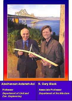
By Abolhassan Astaneh-Asl,
(Professor of Civil Engineering) and
R. Gary Black, (Assoc. professor of Architecture)
University of California, Berkeley
The innovative bridge
design discussed herein is a long span curved cable stayed bridge with a
single canted tower and curved deck. The superstructure of the bridge consists
of a multi-cell steel box girder with composite concrete-steel deck. The
single tower of the bridge is a malt- cell steel box with the core cell
dedicated to the service elevator and stairs. The outer cells of the single
tower are filled with high strength concrete to provide strength and stiffness
in a composite action. The foundation of the main single tower is a solid
footing embedded in the rock. Inelastic time history analyses were conducted
to complete the seismic design and establish expected seismic performance.
After description of architectural design, seismological, geotechnical and
structural design aspects are discussed and a summary of seismic design
and expected seismic response of the curved cable-stayed bridge concept
are presented.
AN INNOVATIVE
CURVED CABLE-STAYED BRIDGE
By Abolhassan Astaneh-Asl,
(Professor of Civil Engineering) and
R. Gary Black, (Assoc. professor of Architecture)
University of California,
Berkeley
The 1989 Loma Prieta earthquake
caused widespread damage to transportation and other civil engineering facilities
in Northern California. The quake caused collapse of a 17m (50ft) long segment
of the San Francisco Oakland Bay Bridge deck and closure of the bridge for
one month for repair and restoration. In the aftermath of the quake, a team
of researchers from the University of California, Berkeley, led by A. Astaneh-Asl,
conducted a seismic study of the East Bay Crossing of the San Francisco
Oakland Bay Bridge (SFOBB) (Astaneh-Asl, 1992). The East Bay and West Bay
Crossings of the San Francisco-Oakland Bay ridge are shown in Fig. 1.
The study identified areas of seismic vulnerability and suggested seismic
retrofit strategies. Later, the California Department of Transportation
conducted an in-house design of seismic retrofit of the East Bay Crossing.
Early in 1997, the State of California, which owns and operates the bridge,
announced that seismic retrofit of the east spans of the Bay Bridge is estimated
to cost about $900 millions. The State also announced plans for a replacement
bridge which was estimated to cost about $1.0 billion. The replacement bridge
consisted of a typical reinforced concrete box girder viaduct supported
on reinforced concrete Tee bents.
To review the issues related to a retrofit or replacement bridge, and to make recommendations to the State on the type of replacement bridge, a Bay Bridge Design Task Force was formed. The members of the Task Force were primarily local elected officials and transportation policy makers. The Task Force then formed an Engineering and Design Advisory Panel (EDAP) to assist the Task Force in recommending a preferred design for a new eastern span of the Bay Bridge. The EDAP developed and issued a Design Criteria to be used in design of new replacement for the East Bay Crossing. The bridge discussed in this paper was one of the designs proposed and is shown in Figures 2,3 and 4. The photomontages are digital graphics.
The Existing East Bay Crossing
is about 9000 ft long connecting the Yerba Beuna Island to the east shore
of the San Francisco Bay. The geotechnical, seismological and environmental
aspects of the site are discussed in the following sections.
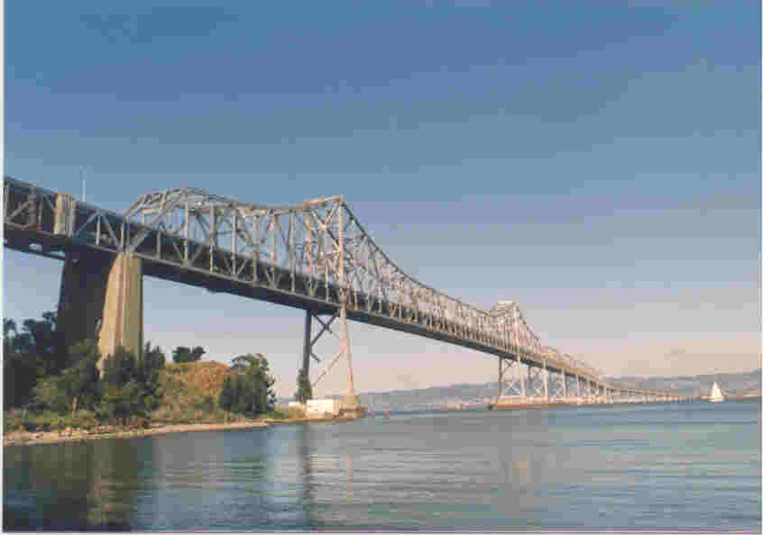 Figure 1. Existing Cantilever Span of the Bay bridge |
THE ARCHITECTURE OF THE PROPOSED BRIDGE (by R.G. Black)
The single tower, cable-stayed
bridge is meant to be consistent with, and pay homage to, the Golden Gate
Bridge and the West Bay Crossing of the San Francisco-Oakland Bay Bridge,
by being a tower and cable bridge. At the same time, it is a visually memorable
landmark and acts as a gateway to Oakland and other cities of the East Bay.
In this respect it must be different from these bridges -- being to the
turn of the millennium what the Golden Gate Bridge and the West Bay Crossing
of the Bay Bridge are to the first part of the Twentieth Century.
The curved deck is suspended by cable stays from a tower which is raked
to balance the forces -- both structurally and visually -- of the weight
of the deck and the traffic. The bridge takes the concept of the suspended
decks of the Golden Gate Bridge and West Bay Crossing of the Bay Bridge
and extends it to another dimension. In these existing bridges the cables
work in two dimensions to pull the forces up and over to the foundations
and land masses so that they can be transferred to the earth. In the curved
bridge, the forces pull the cables in three dimensions -- upward, over to
the tower and back -- acting as a rein on the bridge deck. The architecture
of the bridge expresses exactly what is occurring structurally.
The bridge deck includes a bicycle path and pedestrian walkway. Guardrails
and handrails are designed to provide transparency to a moving vehicle.
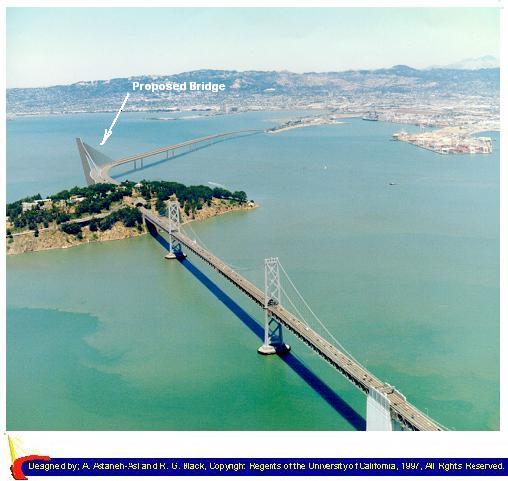
Figure 2. Aerial View of Proposed Bridge
(Digital Photo Montage by C. Peri, UC-Berkeley)
|
|
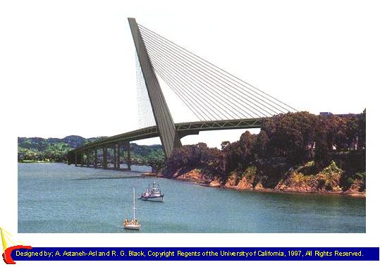
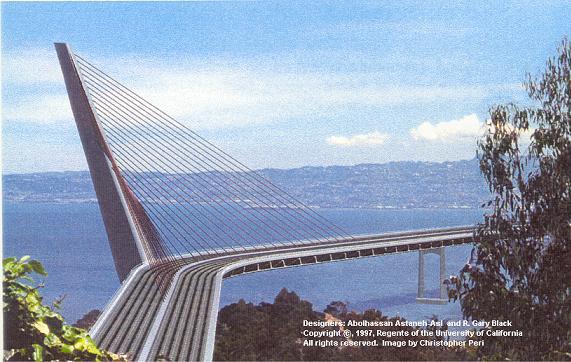 Figure 4. View of the Proposed Design From West |
THE STRUCTURAL AND SEISMIC DESIGN ASPECTS (By A. Astaneh-Asl)
GEOLOGY OF THE SITE
At the site of the bridge, the top of bed rock is estimated to be more than 400 ft below water surface. On top of the bedrock, there is a 300 to 400 ft layer of alluvial soil. A layer of Bay Mud rests on top of the soil. The depth of Bay Mud varies considerably throughout the site.
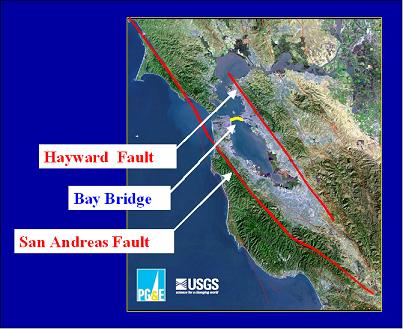
SEISMOLOGICAL ASPECTS
The site of the new bridge, as shown in Fig. 5, is located between the two most active faults of northern California; the Hayward and San Andreas faults. In the aftermath of the Loma Prieta earthquake, a comprehensive study of seismic vulnerabilities of the existing East Bay Crossing was conducted by A. Astaneh-Asl et al. (1992). As part of these studies, seismic aspects of the site as well as activities of the Hayward and San Andreas faults were studied by Bolt and Gregor (1993). The studies resulted in development of synthesized ground motions for the site. Fig. 6 shows the acceleration response spectra used to generate acceleration time-histories used in the the design and inelastic analysis of the proposed bridge.
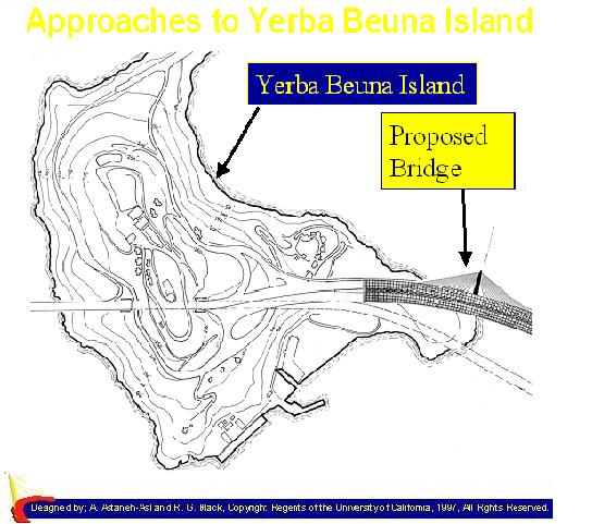
The amplification of ground motion at the Yerba Beuna Island occurs only for very short period range of up to 0.5 seconds. This is due to the fact that Yerba Beuna Island is a rock outcropping. As a result, to minimize the seismic amplification in the proposed bridge design, Yerba Beuna Island was chosen as the location of the main tower of the bridge. Also, it was decided that there will be only one tower founded on the Yerba Beuna Island since there is no other location in the entire length of the East Bay Crossing where the bedrock can be reached at economical depth for foundations to be still economical.
|
|
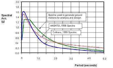 Figure 6. Spectra Used to Generate Acceleration Time Histories |
Various alignments were studies
for the bridge. A straight bridge alignment would place the main span almost
right on an underwater mud-channel formed by mud filling the pre-ice age
river bed. The river currently is Temescal Creek in the East Bay.
One of the reasons for curved alignment of the proposed bridge was to skirt
the Temescal Young Bay Mud channel and support the bridge on stronger and
firmer soil strata. There were several other advantages in using a curved
deck such as aesthetic and structural stability and making the length of
the bridge shorter as well as having less environmental impact. Figure 7
shows the alignment of the existing bridge, the alignment proposed by Caltrans
for the replacement and the alignment for the proposed curved cable-stayed
bridge. Figure 8 shows the proposed bridge at the right side tip of Yerba
Beuna Island.
|
Figure 7. Yerba Beuna Island and the Bridge |
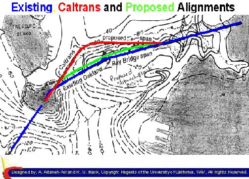 Figure 8. Alignments |
STRUCTURE OF THE MAIN SPAN
The location of the proposed
bridge, as well as the existing suspension part of the Bay bridge is shown
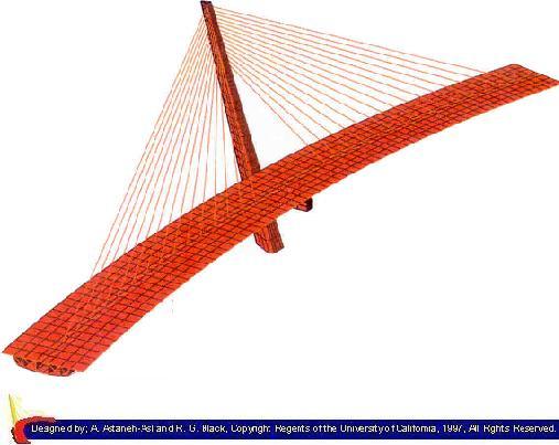
in Figure 2. The proposed bridge, shown in Figures 3, 4, 9 and 10, consists
of two parts: (i) an 1,800 feet long steel single tower, curved cable stayed
bridge with its single tower on the Yerba Beuna Island and (ii) an approximately
8,500 feet long causeway connecting the cable stayed bridge to the Toll
Plaza on the Oakland shore.
By choosing steel as the primary material for the design, the following
advantages are achieved:
· The flexibility of
steel enables a graceful curved design and sloped tower for an elegant appearance
and a reliable structural and seismic performance.
· The curved design results in a shorter bridge length saving in
cost of construction, maintenance and the gas and time spent by drivers
through the 150 years design life of the bridge. The shorter length also
reduces the environmental disturbance of the Bay.
· The light weight of the proposed bridge, 50% less than comparable
concrete designs, results in considerable savings in the cost of construction
as well as reducing the seismic forces.
· High-performance weathering steel, used in our proposed bridge,
provides protection against corrosion and eliminates the need for painting.
Any painting of outside surfaces for aesthetic reasons will last for at
least forty years and possibly longer in the East Bay environment.
|
|
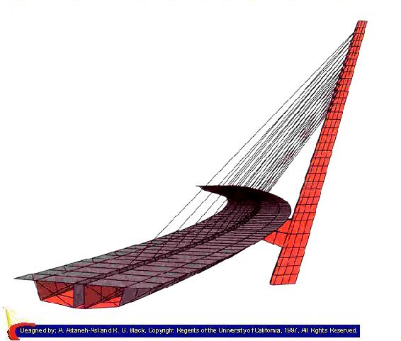 Figure 10. Analytical Model of the proposed Bridge |
Foundations
By placing the main tower on
the solid rock of the Yerba Beuna Island, we have reduced the foundation
to a bare minimum. In addition, the seismic forces transmitted to the structure
through the main tower are reduced significantly compared to forces in an
offshore caisson or a pile-supported foundation. The foundation at this
conceptual stage is tentatively considered to be excavated within the solid
rock and after placing the tower base the grillage is filled with concrete
with possible local reinforcements. The grillage consists of a steel multi-
cell box with wall reinforced openings for concrete embedment. The steel
grillage is extended upward from the top of the foundation to become the
base of the tower. The first jacket units of the tower will be connected
to this base extension and the erection of the other tower jackets will
continue.
The Sloped Tower
The tower, at this conceptual stage, is considered to be a steel composite section. The cross section of tower consists of a steel shell outside and concrete inside with a circular utility and elevator shaft at C.G. of cross section. The tension side of tower is narrower and has more steel while the compression side is wider to take advantage of compressive strength of concrete.
The Bents Used at the End Piers of the Main Cable-Stayed Bridge
The bents at the location of end piers of main cable-stayed bridge are tentatively considered to be U-shaped bents.
The Support Articulations
The end supports consist of
an expansion bearing free to move in longitudinal (tangential) direction
and restrained in transverse (radial direction). The bearing allows bending
rotations to take place both in vertical and horizontal planes. In addition,
two tie downs one on each side of the bearing connect the superstructure
to top of the pier. The main purpose of the tie downs is to restrain torsional
movements at the end supports. If further analyses and design mandates the
use of dampers, such devices will be placed at the end locations to dampen
the longitudinal movements.
The support at the location of main tower consists of a fixed bearing that
restrains movement in both longitudinal and transverse directions but allows
bending rotations to take place in both vertical and horizontal planes.
Similar to end supports, two tie down arms are used here to restrain torsional
movements at the location of the support.
The Superstructure of the Bridge
The superstructure of the proposed bridge is mainly a curved multi-cell steel box girder supported by the cable stays and a single sloped tower as shown in Figures 5 and 6. The roadway is a lightweight reinforced concrete slab supported on stringers and floor beams. In the mid-portion of the box, the top flange consists of steel plate supporting the lightweight concrete slab and acting as composite with the slab. Outside this area, the top flange of the box is only lightweight concrete slab acting as composite with the webs and bottom flange of the steel box. The superstructure of the bridge is supported on three articulated supports; one at the location of tower and two at the location of the end piers. The details of these supports were discussed in the previous section.
The Expansion Joints
The expansion joints are located at the end supports of the main cable stayed bridge. For the causeway section, depending on the final design of the superstructure, necessary expansion joints will be provided.
The Cable-Stays
The cables of the bridge will be 0.6" diameter galvanized wires with co-extruded HDPE pipe on it. To control dynamic wind response of the cables, viscous or rubber based dampers will be installed at the deck anchorage areas, if necessary. No cable ties, which usually does not enhance the appearance will be needed.
Material
The steel used for the bridge
will be high-performance weathering steel. Weathering steel has been used
successfully since 1960's throughout the US including California. This type
of steel does not need painting. However, if the outside surface is painted
for aesthetic reasons, the cost of painting the bridge every 40 years or
so will be considered in the final cost estimate. The high-performance weathering
steel has a higher strength than the regular steel and more importantly
it has increased ductility. The higher strength results in cost efficiency
and the increased ductility leads to an excellent seismic performance of
the bridge.
STRUCTURAL AND SEISMIC DESIGN
The bridge was designed to
resist the effects of dead load, live load, temperature change and seismic
event due to a magnitude 7.3 rupture of the nearby Hayward fault. The load
combinations considered in design were: (a) dead load plus live load of
traffic as per AASHTO-LRFD (1994), and; (b) Dead load, live load and seismic
ground motions of Hayward fault rupture.
The wind load was not considered in design load combinations. This was because
of proximity of the site of bridge to two major faults, seismic effects
were governing at global level. However, wind effects on the geometry of
the deck as well as on possible vibration of stay cables were considered
at the local level. The authors believe that for final wind design of a
bridge of this size, especially with innovative architecture and structural
configurations, wind tunnel tests need to be conducted.
Static and dynamic analyses conducted indicate that the behavior of the
curved cable-stayed structure under gravity, wind, earthquakes and the combined
effects of these loads are stable and desirable. The flutter and vortex
shedding effects due to wind are expected to be insignificant. This is primarily
due to the use of the streamlined cross section of the steel box, Figure
6, and the tripod nature of the curved structure supported at three corners
of a triangle.
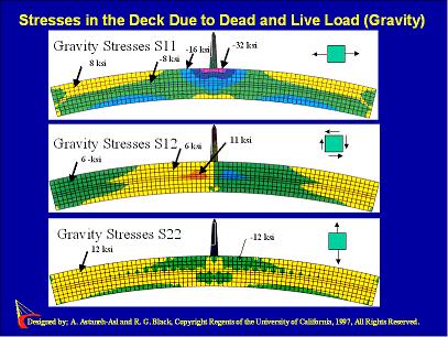
Figure 11 shows gravity load
stresses in the upper flange of the steel box. In designing the deck, a
number of alternate positions for live load were considered. Since this
bridge has very heavy traffic on it, more than 280,000 vehicles per day,
there are various scenarios for traffic jams on various lanes. Therefore
it was deemed necessary to analyze the bridge with full dead load but partial
live load placed in a way that it can create maximum bending and torsional
effects. The studies indicated that when the live load was placed on all
five westbound lanes (the upper half of the curve) and no live load on the
five eastbound lanes (the lower half of the curve) the forces in the superstructure
were the largest. The stresses shown in Figure 11 are for this condition
of loading. The combined stresses did not exceed the yield stress of the
steel used in the superstructure, which is 480 MPa (70 ksi) high performance
steel.
|
|
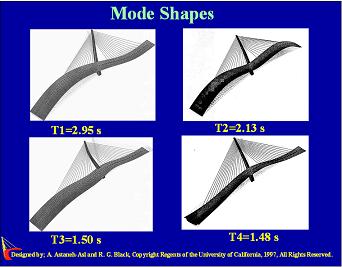 Figure 12. First Four Modes of Vibration |
The same dead load and live
load combination as discussed in above section was considered in seismic
analyses. Seismic analyses were conducted by building an elastic model of
the main span as well as a 3-span segment of the causeway and subjecting
the models to three components of base excitations. In the analytical model
the box girder of the deck was modeled using shell elements for the steel
plates and concrete slab and beam-column elements for the rolled members
used as stiffeners for the shells. The foundation, embedded in the rock
was modeled as fixed support. However, for final design, and after obtaining
bore-hole data on the static and dynamic properties of the supporting rock,
especially for the location of the main tower, rigorous soil-structure-
interaction studies should be conducted and proper stiffness and damping
matrices be assigned to the base of the tower. The 3-span segment of causeway
was the segment immediately to the east of the main cable-stayed span.
Figure 12 shows first four modes of vibration of curved cable stayed bridge.
The first significant mode with a relatively large mass participation was
mode 3, which is essentially a longitudinal mode. Mode 4 was the second
significant mode with a mass participation of about 32%. This mode was essentially
the transverse mode of the vibration (radial direction of the curve). One
interesting observation is that for this curved cable stayed bridge the
cumulative mass participation is about 72% just after only 3 modes.
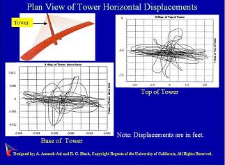
Figure 13 shows movements of top of the tower in horizontal x and y directions.
The x and y directions are longitudinal and transverse directions of the
bridge respectively. Maximum drift ratio (horizontal displacement/ height)
at top of tower was about 1.45%. Figure 14 shows horizontal force at the
abutment support.
|
|
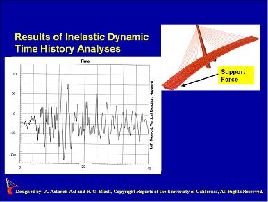 Figure 14. Time History of Force at the Abutment |
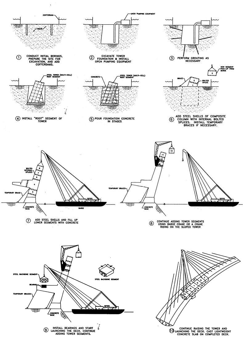
CONSTRUCTION ASPECTS
One of the major considerations in design of long span bridges is construction
sequence. The construction sequence for the curved cable-stayed bridge is
shown in Figure 15. After excavation in the rock island of Yerba Beuna,
the base of tower will be placed in the excavated area and after adding
nominal reinforcements, the concrete foundation will be cast. The next step
is to add prefabricated segments of the tower. The segments that are steel
box sections are field-bolted to each other. As the tower rises above the
cable attachment level, the prefabricated deck segments will be added on
both sides of the tower. These deck segments will be connected to the tower
by their corresponding stay cables. As the tower rises further, more deck
segments are added. In essence, the rising of tower and extension of the
deck on both sides of the tower are synchronized such that after adding
the top segment of the tower, the last segments of the deck will be added.
As the construction of steel tower and steel segments of deck continues,
the concrete deck is cast starting from the tower base and moving out in
both directions. In the meantime, the concrete will be pumped inside the
outer cells of the tower. Finally, the last cable adjustments will be made
to have the bridge deck at exact position for dead load.
|
Figure 15. Sequence of Construction |
CONCLUSIONS
The curved cable-stayed bridge designed by the authors and presented herein
had the following structural and seismic characteristics:
1. The main span of the proposed bridge is a curved cable stayed bridge
supported on single canted tower located at the apex of the arch. The slope
of the canted tower and radius of the deck is designed to ensure that under
the gravity load, the center of gravity of the entire main span passes through
the center of the foundation of the main tower, providing a "stable-equilibrium"
for the bridge.
2. The canted tower acts as a balancing mass bringing the center of gravity
of the entire bridge to location of the foundation of main tower. As a result,
under gravity load, the bridge is in state of stable equilibrium.
3. Because of curved deck, the dominant mode shapes were quite different
from the mode shapes expected of straight bridges. The torsional modes were
not dominant in this curved cable stayed bridge. The reason is related to
the fact that the curved deck is a three dimensional structure supported
at three locations: the main tower and end priers. This results in the superstructure
acting as a "tripod" under dynamic effects and being quite stable
against torsion modes.
4. The response of bridge to the artificial magnitude 7.3 earthquake was
essentially elastic. The ground motions used in the analysis were generated
to represent the Maximum Credible Earthquakes emanating from the nearby
Hayward Fault when it ruptures.
5. A construction sequence for the bridge was developed and proposed. Following
the proposed sequence, after construction of the foundation of the main
tower, the superstructure of the bridge can be constructed "growing"
from the foundation without any need to disturb the delicate environment
of the Yerba Beuna Island where the main tower is located.
REFERENCES
AASHTO. (1994). "AASHTO LRFD bridge design specification". American Association of State Highway and Transportation Officials.
AASHTO. (1999). "AASHTO LRFD bridge design specification". American Association of State Highway and Transportation Officials.
Astaneh-Asl, A., Bertero, V., Bolt, B., Mahin, S., Moehle, J. and Seed, R. (1989). "Preliminary report on the seismological and engineering aspects of the October 17, 1989 Santa Cruz (Loma Prieta) earthquake', Report, UCB/EERC -89/14, Univ. of California, Berkeley.
Astaneh-Asl, A. (1990). "Damage to San Francisco Oakland Bay Bridge" Report to the Governor's Board of Inquiry on Loma Prieta Earthquake, Dept. of Civil and Env. Engrg., Univ. of California, Berkeley.
Astaneh-Asl, A. (1992a). "Seismic studies of the San Francisco-Oakland Bay Bridge." Proc., 10th World Conf. on Earthquake Engrg., Association Española de Ingeniería Sísmica, Madrid, Spain.
Astaneh-Asl, A.(1992b). "Seismic retrofit concepts for the Bay Bridge." Report to California Dept. of Transportation, Dept. of Civil and Env. Engrg., University of California, Berkeley.
Astaneh-Asl, A. (1994). "Seismic
retrofit concepts for the East Bay Crossing of the San Francisco-Oakland
Bay bridge." Proc.,, Fifth US National Conf. On Earthquake Engrg. Earthquake
Engineering Research Institute, Chicago, Illinois.
Astaneh-Asl, A. (2001) " Seismic retrofit concepts for the east spans
of the San Francisco Bay bridge", Proc. Structural Faults and Repair-2001,
Commonwealth Institute, London.
Astaneh-Asl, A., McMullin, K., Wang, K., and Suharwardi, I. (1993). "Seismic
condition assessment of the East Bay crossing of the San Francisco-Oakland
Bay Bridge, Volume 6: Three-dimensional elastic time-history dynamic analyses."
Report No. UCB/CEE- Steel- 93/08, Department of Civil and Environmental
Engineering, University of California, Berkeley.
Astaneh-Asl, A. (1997). "The steel curved cable-stayed bridge designs: 1. The sloped tower design and; 2. The vertical tower design." Report No. UCB/CEE-Steel- 97/05, Department of Civil and Environmental Engineering University of California, Berkeley.
Astaneh-Asl, A. and Ravat, S. (1998). "Cyclic behavior and seismic design of steel H-piles." Report No. UCB/CEE-Steel- 98/01, Department of Civil and Environmental Engineering, University of California, Berkeley, May.
ASTM, (2000), "Standard Specification for Carbon and High-Strength Low-Alloy Structural Steel Shapes, Plates, and bars and Quenched-and-Tempered Alloy Structural Steel Plates for Bridges", Annual Book of ASTM Standards, American Society for Testing and Materials, West Conshohocken, PA.
Bolt, B. and Gregor, N., (1993) , "Synthesized strong ground motions for the seismic condition assessment of the eastern portion of the San Francisco Bay Bridge", Report No. UCB/EERC-93/12, University of California, Berkeley.
Caltrans (1999). "Caltrans seismic design criteria, Version 1.1". Technical Report, California Department of Transportation, Sacramento.
DMG. (1969), "Geologic and engineering aspects of San Francisco Bay fill", California Division of Mines and Geology, Special Report 97.
Rogers, J. D., and S. H. Figures, (1991). "Engineering geologic site characterization of the greater Oakland-Alameda area, Alameda and San Francisco counties, California", Report to the National Science Foundation, Grant No BCS-9003785.
Shen, J. H. and Astaneh-Asl, A. (1993). "Hysteresis behavior and modeling of double-angle semi-rigid connections." Report No. UCB/CE-Steel-93/10. Department of Civil and Environmental Engineering, University of California, Berkeley, December.
Trask, P.D. and Rolston, J. W. (1951). "Engineering geology of San Francisco Bay, California", Bulletin of the Geological Society of America, Vol. 62, pp. 1079-1110. September.
|
02-Astaneh-Asl, A. and Black,
R.G. (2001) "Seismic and Structural Engineering of a Curved Cable-Stayed
Bridge", J. of Bridge Engineering, ASCE, Vol. 6, No.6, Nov/Dec pp. 439-450.
01-Astaneh-Asl, A. (1997). "The steel curved cable-stayed bridge designs:
1. The sloped tower design and; 2. The vertical tower design." Report
No. UCB/CEE-Steel- 97/05, Department of Civil and Environmental Engineering
University of California, Berkeley.
DESIGN TEAM AND ACKNOWLEDGMENT
|
|
The information presented here
has been prepared in accordance with recognized engineering principles and
is for general information only. While it is believed to be accurate, this
information should not be used or relied upon for any specific application
without competent professional examination and verification of its accuracy,
suitability, and applicability by a licensed professional engineer, designer
or architect. The publication of the material contained herein is not intended
as a representation or warranty on the part of any person or agency named
herein, that this information is suitable for any general or particular use
or of freedom from infringement of any patent or patents. Anyone making use
of this information assumes all liability arising from such use. Caution must
be exercised when relying upon specifications and codes developed by others
and incorporated by reference herein since such material may be modified or
amended from time to time subsequent to the posting of this material. The
authors bear no responsibility for such material other than to refer to it
and incorporate it by reference at the time of the initial posting of this
document.
( to purchase a copy of these
reports, please see above note
under "Publications").
Astaneh-Asl, A. (1997). "The steel curved cable-stayed bridge designs:
1. The sloped tower design and; 2. The vertical tower design." Report
No. UCB/CEE-Steel- 97/05, Department of Civil and Environmental Engineering
University of California, Berkeley.